|
|

Adding Elements to a Model |

|

|

|
||
Adding Elements to a Model |
|
|
|

|
|
|
Adding Elements to a Model |
|
|
|
||
Adding Elements to a Model |
|
|
|
|
|
|
||
Elements are added to the model by selecting an element button on the tool palette and clicking the wanted position on the diagram. Adding several elements of the same type after each other can be done by double clicking the element selection on the tool palette. After this just place the elements on the diagram view.
![]() Exercise 51: Add elements to the model.
Exercise 51: Add elements to the model.
| 1. Create a new model using the Default settings template. |
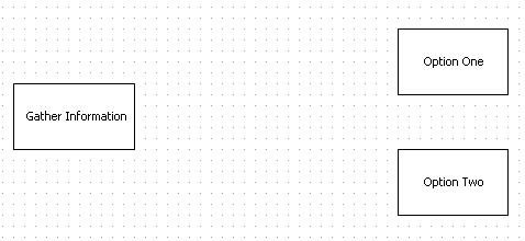
| 2. On the Tool Palette, double-click the Activity process step. |
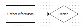
| 3. Click on the diagram to create new Activity process steps somewhat as in the picture below: |
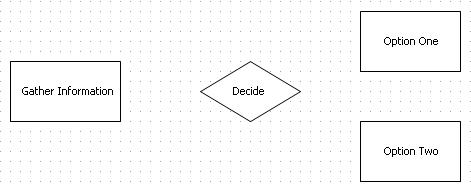
| 4. On the Tool Palette, click the Decision process step. |
| 5. Click on the diagram to create a new Decision process step so that the diagram will look somewhat as in the picture below: |
Note that when you don't double click a process step on the Tool Palette, you can only create one process step of the chosen type at one selection
| 6. Save the model. |
One way to add elements to a model is to drag the desired element from the Tool Palette to the diagram.
![]() Exercise 52: Add elements to the model using Drag & Drop drawing.
Exercise 52: Add elements to the model using Drag & Drop drawing.
| 1. Create a new model using the Default settings template. |
| 2. On the Tool Palette, click the Activity button and hold the mouse button down, and drag the element on the diagram: |
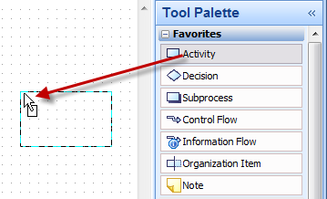
| 3. Drag the Activity element to the desired location and release the mouse button. The element will be created on the location where you release the mouse button. |
| 4. Repeat step number two. |
| 5. Press the Esc key. The element creation is canceled. Another way to cancel the element creation is to drag the mouse pointer outside the diagram area and then release the mouse button. |
Another way to add elements to a model is to use Quick Modeling. When using Quick Modeling, a connector connecting the elements is created with the new element.
![]() Exercise 53: Add elements to the model using Quick Modeling.
Exercise 53: Add elements to the model using Quick Modeling.
| 1. Create a new model using the Default settings template. |
| 2. On the Tool Palette, click the Activity process step. |
| 3. Click on the diagram to create new Activity process step. |
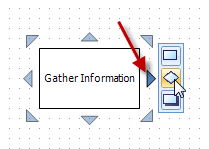
| 4. Point the mouse over the newly created process step in order to make the Quick Modeling hotspots visible. |
| 5. Point the mouse over a hotspot and click the element in the middle of the menu that opens: |
| 6. A Decision type process step will be created, and the two process steps are connected with a connector. Give the newly created process step a name: |
More information about Quick Modeling can be found in the QPR Modeling Client - User's Guide under the Quick Modeling topic.
QPR Modeling Client features alignment guides that help in aligning the elements on the diagram. Before doing the following exercise, make sure the alignment guides are enabled from the Options Dialog accessible from the Application Menu.
![]() Exercise 54: Use alignment guides.
Exercise 54: Use alignment guides.
| 1. Create a new model using the Default settings template. |
| 2. On the Tool Palette, double-click the Activity button. |
| 3. Click three times on the diagram to create three elements, and name them. |
| 4. Click the second element, and holding the mouse button down, drag the second element next to the first element so that the alignment guide is visible in the middle of the elements: |
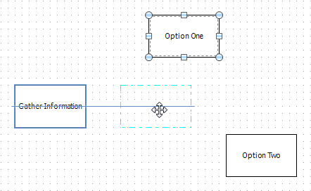
| 5. Release the mouse button. |
| 6. Click the third element, and holding the mouse button down drag the third element next to the second element so that the alignment guide is visible in the middle of the elements: |
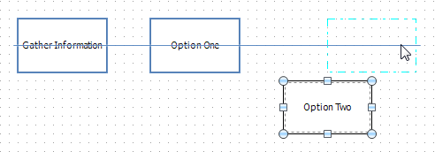
| 7. Drag the third element closer to the second element until the arrows on the alignment guide become visible: |
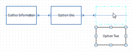
| 8. Release the mouse button. The distance from the middle element to the neighboring elements is now even and the elements are aligned. |