|
|

Modeling Options Dialog |

|

|

|
||
Modeling Options Dialog |
|
|
|

|
|
|
Modeling Options Dialog |
|
|
|
||
Modeling Options Dialog |
|
|
|
|
|
|
||
The Modeling Options dialog is used to control which modeling elements are used and how they are represented in the diagrams.
The Modeling Options dialog can be accessed by selecting Modeling Options on the Model tab of the ribbon.
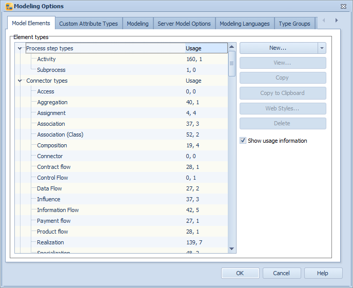
Modeling options dialog
Model Elements
In the Model Elements section of this dialog the element types can be selected from a list. In addition, new element types can be created and existing ones can be modified or deleted.
The use of the following model elements can be decided:
![]() information stores
information stores
![]() material stores
material stores
![]() notes
notes
![]() groups
groups
If these options are left unchecked, they are not used for modeling. Also, the use of drawing elements (i.e. checkpoints, texts and pictures) in the diagrams can be selected. Note that changing these options requires that the model is reserved for exclusive editing.
![]()
![]() The dynamic web publishing settings can be defined by selecting an element type from the list and clicking the Web Styles button.
The dynamic web publishing settings can be defined by selecting an element type from the list and clicking the Web Styles button.
![]() Creating almost identical process step types, element types, and connector types can be done by clicking the Copy button, and then changing the settings of the copied type. The created copy will have an incremental number added to the name of the copied element. Note that Web Styles and Descriptions are not copied. This feature is available with a separate license.
Creating almost identical process step types, element types, and connector types can be done by clicking the Copy button, and then changing the settings of the copied type. The created copy will have an incremental number added to the name of the copied element. Note that Web Styles and Descriptions are not copied. This feature is available with a separate license.
![]() In case the Metamodel Browsing feature is enabled by your license, you can use the Copy to Clipboard button with element types and type groups to copy them to other models. For element types, the element type along with its custom attribute definitions is then copied to clipboard and can be pasted to another model. The element type is matched with the symbol attribute and no duplicate types are created. A new Tool Palette stencil is then also created. Similarly for type groups, the type group definitions are copied and when you paste them to another model, a new type group is created. Note that the target model has to have the element types, attribute types, stencils and view settings already in existence, since they are not copied with the type group but only the type group definition is copied.
In case the Metamodel Browsing feature is enabled by your license, you can use the Copy to Clipboard button with element types and type groups to copy them to other models. For element types, the element type along with its custom attribute definitions is then copied to clipboard and can be pasted to another model. The element type is matched with the symbol attribute and no duplicate types are created. A new Tool Palette stencil is then also created. Similarly for type groups, the type group definitions are copied and when you paste them to another model, a new type group is created. Note that the target model has to have the element types, attribute types, stencils and view settings already in existence, since they are not copied with the type group but only the type group definition is copied.
![]() Also, if your license includes the Metamodel Browsing feature, you can enable usage information to be shown in the Element types hierarchy by selecting the "Show usage information" checkbox. By default, this information is not shown. When this checkbox has been selected, the number of elements of each particular type for process step, connector and element types is shown in the "Usage" column.
Also, if your license includes the Metamodel Browsing feature, you can enable usage information to be shown in the Element types hierarchy by selecting the "Show usage information" checkbox. By default, this information is not shown. When this checkbox has been selected, the number of elements of each particular type for process step, connector and element types is shown in the "Usage" column.
Process Step Types
Process step types can be modified using the New, View and Delete buttons. Selecting New or View will open the Process Step Type dialog in which process step type properties can be defined. The modeling options must have at least one subprocess type defined, so the last subprocess type cannot be deleted.
Deleting a process step type when process steps of that type exist in the model will result a special deletion situation. Since process steps cannot exist without belonging to a process step type, when the process step type is deleted, another dialog will appear with which you can select a substitute process step type for the process steps. Once you have clicked OK, all the process steps of the deleted type will now belong to the selected substitute process step type.
Additionally, if the model is a base model, a message will appear stating that child models might contain process steps of the type that is being deleted, and you are requested to choose a process step with which the deleted process step type will be substituted in the child models.
A process step type can be assigned a name, type and a description. If the selected type is "Subprocess", then every process step of that type can be further modeled in more detail on a lower process level. If the process step is of the type "External Model", then the process step acts as a link to another complete model. Information containers are process steps which contain an information item similarly as information flows, but they are not visible in the Report view, and appear in the Navigator view and in element selection lists with a distinctive icon. Activities are the "normal" activities (such as Activities and Decisions) which appear on a single process level only. Main process is used for the main process level element and it functions in the same way as the subprocess process step type except that the main process process step type can be deleted whereas the subprocess cannot be.
Furthermore, a symbol, default graphical properties and custom attribute types can be defined for a process step type.
Connector Types
Connector types can be modified using the New, View, and Delete buttons. Selecting New or View will open the Connector Type dialog in which connector type properties can be defined.
Deleting a connector type when connectors of that type exist in the model will result in a special deletion situation. Since connectors cannot exist without belonging to a connector type, when the connector type is deleted, another dialog will appear with which you can select a substitute connector type for the connectors. However, if the last connector type is deleted, all connectors are removed from the model. Once you have clicked OK, all the connectors of the deleted type will now belong to the selected substitute connector type.
A connector type can be assigned a name and a description. In addition, the connector type can be set as an "Information flow".
Furthermore, a symbol, default graphical properties and custom attribute types can be defined for the connector type.
Element Types
Generic element types can be modified using the New, View, and Delete buttons. Selecting New or View will open the Element Type dialog, in which properties for generic element types can be defined.
Deleting an element type when generic elements of that type exist in the model will result in a special deletion situation. Since generic elements cannot exist without belonging to an element type, when the element type is deleted, another dialog will appear with which you can select a substitute element type for the generic elements. Once you have clicked OK, all the generic elements of the deleted type will now belong to the selected substitute element type.
An element type can be assigned a name and a description. In addition, some predefined behavior properties can be defined for the element type.
Furthermore, a symbol, default graphical properties, and custom attribute types can be defined for an element type. Note that if a symbol has not been defined for an element type, elements of that type cannot be drawn on the diagram.
Used Elements
For process step types, custom element types, connector types, groups, information stores, material stores, and notes, a symbol to represent these model elements can be selected. For all the model elements default graphical properties can be defined. For process step types, connector types, groups, information stores, material stores, notes, organization items, measures, cases, information items, and resources, custom attribute types can be defined.
The quick modeling settings, default graphical properties, and custom attribute types can be viewed and modified from the Modeling Options dialog by clicking the View button on the right of the desired element.
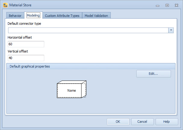
Modeling Tab of the Material Store Dialog
Click the Edit... button to modify the graphical properties.
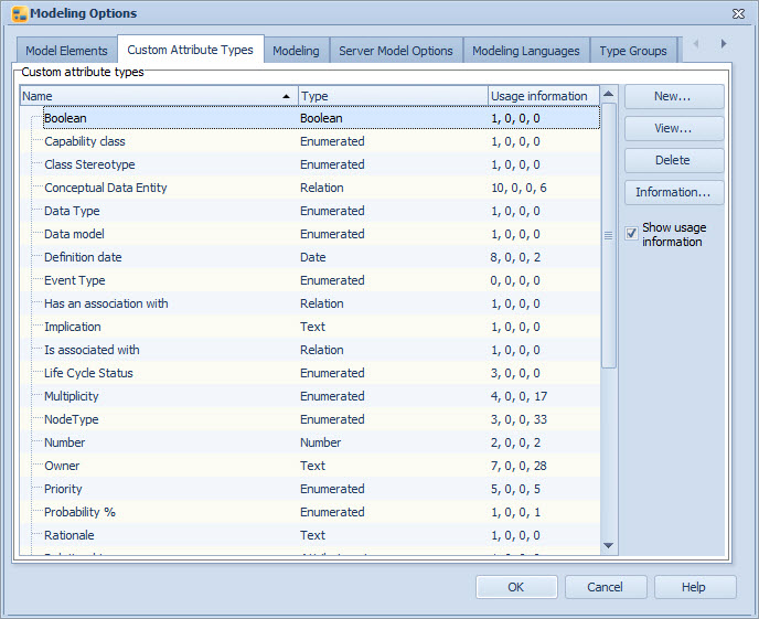
Custom Attribute Types
The Custom Attribute Types tab contains a list showing all attributes in the model and their types. In this tab you can create and modify custom attribute types and remove them. To create a new custom attribute type, select New... To modify an existing custom attribute type, select View... A new dialog opens where you can edit the custom attribute types. To remove a custom attribute type, select Delete.
![]() In case the Metamodel Browsing feature is enabled by your license, you can select usage information on the attribute type to also be shown by selecting the "Show usage information" checkbox. When this checkbox has been selected, the following information is shown in the "Usage information" column (separated by commas):
In case the Metamodel Browsing feature is enabled by your license, you can select usage information on the attribute type to also be shown by selecting the "Show usage information" checkbox. When this checkbox has been selected, the following information is shown in the "Usage information" column (separated by commas):
•number of element types using the attribute type
•number of attribute types sets & enumerated values using the attribute type
•number of relation connectors setting this value
•number of elements having a value for this attribute
To have more detailed usage information for the particular attribute type shown, select Information... (or press CTRL and double-click the attribute type). The Attribute Type Information Dialog opens.
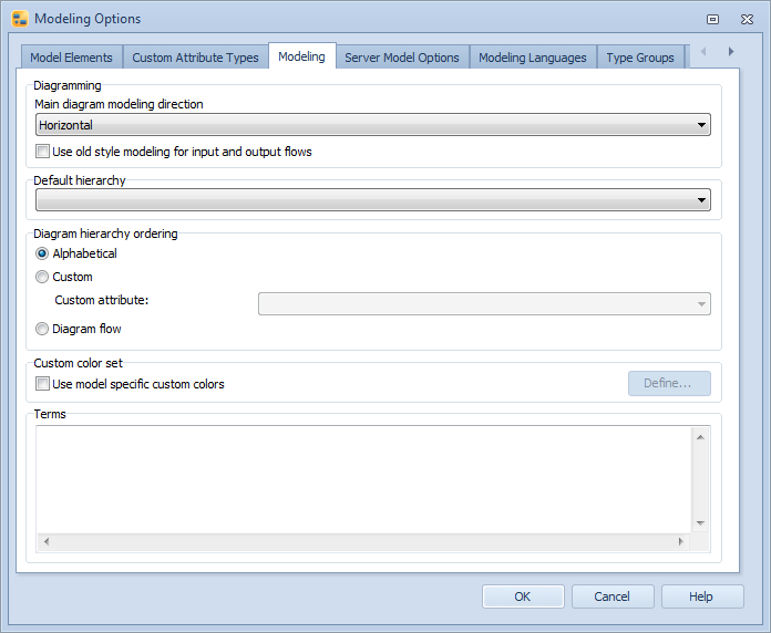
Modeling
The Modeling tab allows you to define various modeling settings.
Main Diagram Modeling Direction
The modeling direction can be set to be either horizontal (organization items are horizontal rows and modeling is usually done from left to right) or vertical (organization items are vertical columns and modeling is usually done from up to down). This setting affects the main diagram. For child diagrams the default direction is always horizontal, but it can be changed in the diagram settings or individually for each child diagram.
The "Use old style modeling for input and output flows" option changes flows to use the old style of modeling for input and output flows, which means that there are circles also at the beginning of input flows and at the end of output flows. In the current style, the circles are drawn only when the flow goes to or comes from some other process level than the parent or a child diagram and the flow does not qualify as an input or an output flow.
Default Hierarchy
The default hierarchy selected from this drop-down menu is the default hierarchy for the elements of the whole model. The hierarchy is used by elements that are not of any specific element type, for example by a relation custom attribute that is a relation to an element. Only one hierarchy can be selected as the default hierarchy for the whole model, and the selection is not mandatory, i.e. it is possible to not have a default hierarchy. When the default hierarchy is set, it is shown when selecting elements that are not of any specific element type. If there are elements that don't belong to the default hierarchy, those elements are listed at the end of the hierarchy list at root level. If the default hierarchy is not set, all elements are listed without a hierarchy when selecting elements that are not of any specific element type.
Diagram Hierarchy Ordering
The ordering method of the elements in the diagram hierarchy can be defined as alphabetical (default), custom, or diagram flow. Selecting "Alphabetical" will sort the elements alphabetically. Selecting "Custom" will sort the elements according to the values of the selected custom attribute. If the custom attribute has several values, the first value is used for the sorting. If two or more elements have the same value, the ordering is random. If the selected custom attribute is not used in a an element type or the element type does not have a value for that custom attribute, the elements of that type are positioned last in the hierarchy. See the Auto Numbering Wizard Dialog for instructions on how to generate the 'Order number' custom attribute values for the elements automatically. Selecting "Diagram flow" will sort the elements as follows:
•If the modeling direction is set to horizontal, the ordering of the elements is done by their X coordinate (from left to right)
•If the modeling direction is set to vertical, the ordering of the elements is done by their Y coordinate (from top to down)
•Elements with the same X coordinate are ordered by the Y coordinate and vice versa
The ordering method affects all the diagram hierarchies, the diagram hierarchy in the diagram view, the navigator view, and all the diagram hierarchies in the QPR Portal.
Custom Color Set
Whenever you define a custom color in the QPR Modeling Client, it is saved for later reuse (it is available also in new models). However, an administrator user can define a custom color set to be used with a certain model and force its usage. If the Use model specific custom colors option is checked, then the Define... button becomes enabled and the administrator user can define the custom colors that are used with the model. If the model specific custom colors are used, users can still define custom colors, but they are not saved with the model. The model specific custom colors are not saved for system-wide reuse like other custom colors and they can be modified only in this dialog.
Terms
In the Terms section you can override terminology used in the model. If you have used terms.ini to customize QPR product terminology, the functionality is similar here, i.e. you can redefine terms used in the model with <original term>=<custom term> syntax, so for instance "Organization Item=Lane" line (without the double quotes) would change all instances of "Organization Item" string (with that exact spelling, i.e. for example Organization item is not affected without adding a separate row for it) to "Lane". If you want the term to be changed regardless of the active user interface language, prefix the string with $, for example "$Organization Item=Lane". Note that the strings you can change here are those coming from the user interface dictionaries selectable in the Options dialog, so for example names of process step types need to be translated in dialogs accessible from the Model Elements tab.
![]()
![]() The terms defined here are stored in the model and available in QPR Portal as well.
The terms defined here are stored in the model and available in QPR Portal as well.
Modeling options dialog - Modeling page
File/Server Model Options
![]()
![]() When you have a Server model open, this page displays the "Server Model Options". When the current model is a file model this page displays the "File Model Options".
When you have a Server model open, this page displays the "Server Model Options". When the current model is a file model this page displays the "File Model Options".
![]() This page displays the "File Model Options".
This page displays the "File Model Options".
File Model Options
On this page the security settings can be defined for the current file model. The two options available are:
Password: This option allows you to define one password for the model. In this case, any user that opens the model and enters the correct password has full access to the model.
If you have selected this option, then enter the model's password and confirm the password by retyping it in the "Retype password" field.
None: Select this option if you do not wish to put any security restrictions on the current file model. In this case, no login is required by the user to open the model.
![]()
![]()
Server Model Options
The Force exclusive option defines how the model can be opened for editing. If the option is checked, then only exclusive editing is allowed. Otherwise many users can modify the model simultaneously, providing that no user has chosen to open the model for exclusive editing.
If the Inherit diagram rights from folder rights option is selected, the diagram rights for the model are defined in the following way:
•User has View Rights to a folder: view rights are applied to all diagrams in the model. Full rights are given to Measures, Resources and Simulation.
•User has Modify Rights to a folder: modify rights are applied to all diagrams in the model.
•User has Folder Administrator rights for a folder: modify rights are applied to all diagrams in the model and the user is set to be a model administrator.
Select the Publish Model check box to publish the current model via the QPR Web Application Server, see dynamic web publishing for more information. To configure the options for publishing a model, select the Web Style Sets... button.
In the bottom of the page you can define the settings for base models. The options available here are different depending on whether the current model is a base model or not. See the Base Models topic for more information about the options and their usage.
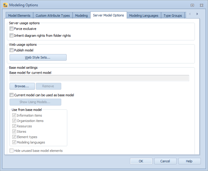
Modeling options dialog - Server model options page
![]()
![]()
Modeling Languages
In the Modeling Languages tab you can enable multilingual modeling to be used in the model and define languages available in the model. In addition, you can define translations for the languages included.
Check the "Enable multilingual modeling" checkbox to take multilingual modeling into use in the model.
The Languages list displays all languages defined for QPR Modeling Client. You can select the languages that are available in the model by checking the checkbox next to the language's name.
To add a new language, click the "New..." button. The Language Properties dialog will open for defining settings for the language. Note that the new language will be available also in other models that are on the same server as the current model.
To view the language's settings, click the "View..." button. The Language Properties dialog will open with the language's information pre-filled.
To delete a language from the list, select the desired language and click the "Delete" button.
Note |
Languages defined in this dialog are used server-wide, so deleting a language deletes it from all models on the same server. |
To set a language as the default language of the current model, select the desired language and click the "Set as Default" button. When initially enabling multilingual modeling, this can be used to define the language of the current terms. For example, if you have a model with element names in Finnish and you enable multilingual modeling and add English, Finnish, and Swedish as the languages, you can (and should) set Finnish as the default language to indicate that the current terms should be marked as the Finnish variants. Note that this functionality is available only when enabling multilingual modeling for the first time. After that, the default language affects only the language that is used as the default, i.e. any translations aren't affected.
The language settings defined on the Modeling Languages tab are model specific. See the Language Properties Dialog for the language properties themselves, which affect all the models on the server using the language in question.
Note that multilingual modeling is not available without a server connection. However, if a file model was created with multilingual modeling enabled, multilingual modeling is available offline.
Tip! It is good to add the organization's official language as the Secondary language in the Language Properties Dialog for each of the multilingual modeling languages. That way, if some translations are missing, there will always be the organization's official language available for the untranslated items.
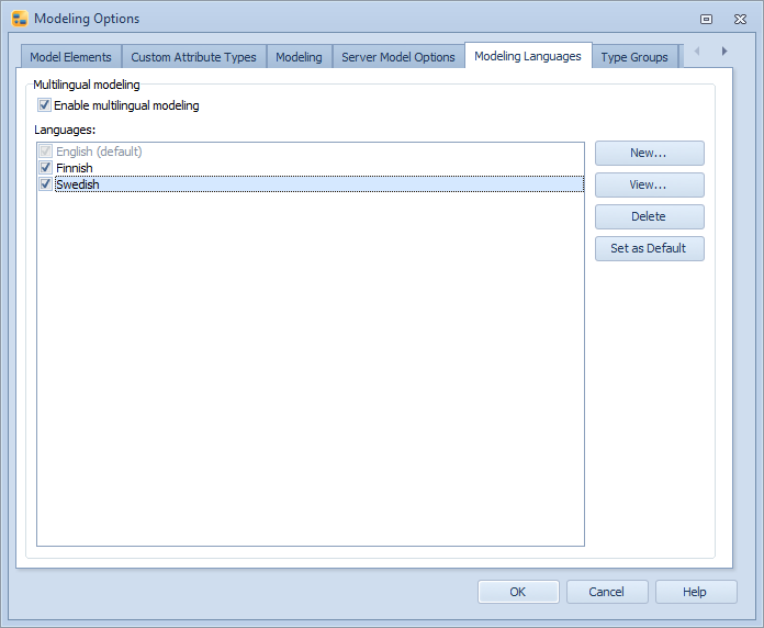
Modeling options dialog - Modeling Languages page
![]()
![]()
Type Groups
By utilizing type groups, you can define which modeling notation is used in which diagrams. Element types, custom attribute types, stencils, and view settings can be collected together in a type group. This group can then be selected in the Tool Palette so that only those stencils belonging to the group are selectable and only those view settings belonging to the group can be selected from the View Settings menu. It is also possible to set the default group for subprocess element types and element types with the diagram modeling behavior enabled. When the default element type group is defined for a subprocess, the element type group is selected in the Tool Palette when you go to the child diagram. To create a new Type Group, click New, or to view or modify an existing Type Group, select the group and click View. The Type Group Properties Dialog will open. Clicking Delete will remove the selected Type Group. In case the Metamodel Browsing feature has been enabled by your license, there is also a "Usage" column which shows the number of Type Groups the element type has been directly assigned to (that is, excluding Type Groups with "all" option).
Type Groups may be available with some separate EA templates.
Model Validation
On the Model Validation tab, you can define validation rules to help you with model consistency and following a modeling notation. When these rules are defined, a validation error icon is shown on the Diagram view if a validation rule is broken. Validation rules defined on the Modeling Options dialog are used as the default rules in the model. Element type specific validation rules defined in the element type dialogs will override the default rules. The validation can be enabled and disabled on the Modeling tab of the Options Dialog.
Things to Note About Model Validation:
•Model Validation warnings are visible only in the Modeling Client, i.e. in QPR Portal, validation warnings are not shown.
•The Diagram view validation warnings can be enabled and disabled in the Diagram View Settings Properties.
•To show validation warnings in the Navigator view, add the 'Validation warning icon' and/or 'Validation warning message' columns in the Navigator View Settings.
•Model Validation settings are inherited from Base Models.
•If elements are copied between models, the model validation settings of the target model are used. In case the target model doesn't contain the copied element type, the element type specific model validation settings are copied with the element type from the source model.
•Model Validation is not available for combined, forked, or joined flows.
•Model Validation settings are not imported or exported via XML import or export.
Connector start and end are connected
The selections in this section will cause a validation error to be reported if the start and/or end of a connector of the selected type are not connected.
Information flow consistency
Selecting this rule will check that an information flow carries only information that is available in the source element. That is, the information item must either be linked to the source element or be brought to the source element via an information flow carrying the information item. If the source element has a parent information item linked to it, the information flow going out of the source element can carry any child information items of the parent information item. If there are information flows bringing all the child information items to the source element, an outgoing information flow can carry the parent information item of the child information items.
Connections
Selecting this rule will enable the model element type specific connection validations.
Script
It is possible to write a validation script that utilizes the QPR API. When a validation script has been defined in the Modeling Options dialog, it will be executed for each changed element after each end of a transaction. The execution can be disabled in the element type specific settings, or if a validation script has been defined in the element type specific settings, that script will be executed instead of the script defined in the Modeling Options dialog. A transaction is one user operation, which can contain several modified elements.
The validation script has only limited access to the QPR API. Only the following PGModel API functions are available: AddValidationWarning, Find, GetActive, GetProperty, GetProperties, GetModelProperty, GetObjectRights, and RemoveValidationWarnings. Only the following PGApplication API functions are available: GetServerModels, SetUIMode, GetErrorMessage, GetProperty, GetObject, CreateFolder, GetUserName, GetUserInfo, GetGroupInfo, GetUserId, Sleep, FileOpenDialog, FileSaveDialog, Delete, and Get_Actions. See QPR - Developer's Guide for descriptions of these functions.