|
|

Cross-model Interface |

|

|

|
||
Cross-model Interface |
|
|
|

|
|
|
Cross-model Interface |
|
|
|
||
Cross-model Interface |
|
|
|
|
|
|
||
![]()
![]() The cross-model interface is a special element type that makes interface elements visible to other models through external model elements.
The cross-model interface is a special element type that makes interface elements visible to other models through external model elements.
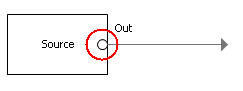
A cross-model interface can be used to define cross model connections and linking, as well as intramodel connections and linking. Since connector cannot directly continue from one model to the other, the cross-model interface can be used to map incoming connector(s) to outgoing connector(s). When the mapping has been done unambiguously, the process flow can be followed in QPR Portal from model to model by clicking the element or by clicking the small circle at the end of the connector shown in the picture below.
![]() A cross-model interface can be used to define intramodel connections and linking. The cross-model interface can be used to map incoming connector(s) to outgoing connector(s).
A cross-model interface can be used to define intramodel connections and linking. The cross-model interface can be used to map incoming connector(s) to outgoing connector(s).
Defining Connector Mappings for the Cross-model Interface
![]()
![]() A cross-model process flow can be defined by mapping an incoming connector from one model to the outgoing connector in the other model. Note that the connectors to be mapped need to be created before doing the mapping.
A cross-model process flow can be defined by mapping an incoming connector from one model to the outgoing connector in the other model. Note that the connectors to be mapped need to be created before doing the mapping.
![]() An intra-model process flow can be defined by mapping an incoming connector to the outgoing connector. Note that the connectors to be mapped need to be created before doing the mapping.
An intra-model process flow can be defined by mapping an incoming connector to the outgoing connector. Note that the connectors to be mapped need to be created before doing the mapping.
To define connector mappings, do the following:
1.Go to the Interface tab on the Custom Element Properties dialog or on the Process Step Properties dialog.
2.Select the Cross-model interface checkbox.
3.Click 'Select' next to the Linked to field, the Select Interface Element dialog opens.
4.In the Select Interface Element dialog, navigate the hierarchy to select the interface element to which you want to add the mapping and click OK.
5.In the Incoming connector mappings section, highlight the desired connector and click 'Select', the Select Interface Element dialog opens.
6.In the Select Interface Element dialog, select the connector to which you want to add the mapping and click OK.
7.In the Outgoing connector mappings section, click 'Select', the Select Interface Element dialog opens.
8.From the Select Interface Element dialog, select the connector to which you want to add the mapping and click OK.
9.Click OK to close the Custom Element Properties dialog.
Note that mapping both incoming and outgoing connectors is not mandatory, you can choose to define the mapping only for an incoming or an outgoing connector. However, there is no link back from the target interface if the mapping has not been done there.