|
|

Tool Palette Stencil Properties Dialog |

|

|

|
||
Tool Palette Stencil Properties Dialog |
|
|
|

|
|
|
Tool Palette Stencil Properties Dialog |
|
|
|
||
Tool Palette Stencil Properties Dialog |
|
|
|
|
|
|
||
In the Tool Palette Stencil Properties dialog you can create new stencils to the Tool Palette or edit existing stencils. This dialog is accessible from the pop-up menu of the Tool Palette.
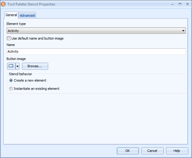
To create a new stencil or edit an existing stencil:
1.Select the element type from the drop down menu in Element type.
2.If you want to use the default name and button image, select the checkbox Use default name and button image. Then the tool palette stencil name is determined by the element type.
3.If you do not want to use the default name, enter the name of the stencil in the Name field.
4.If you do not want to use the default button image, click the downward arrow below Button image to select the image from a predefined set of button symbols, or click Browse... to select your own image. Only bitmap images can be used.
5.If you select Create a new element as the Stencil behavior, drawing an element will create a new element, and an instance is created by drawing the element with the Ctrl key pressed down. If you select Instantiate an existing element, drawing an element will instantiate an existing element, and a new element will be created by drawing the element with the Ctrl key pressed down.
6.If the element type you selected has custom attributes defined in Modeling Options, you can add them to the stencil. The element types checkpoint, picture, and text cannot have custom attributes. To add attribute values, switch to the Advanced tab, click Add in the Attribute values section, and write the attribute's value to the Value field. You cannot add relation, attribute set, or enumerated type attributes for the stencils. In addition, if the element type you selected has been defined as a cross-model interface in Modeling Options, you can add the cross-model interface as an attribute. The values you enter are set to the new elements when they are created using the tool stencil. To remove an attribute and its value, select the attribute and click Remove. When an existing element is instantiated, the stencil's predefined attribute values are ignored.
7.If you want to edit the graphical properties of the stencil, switch to the Advanced tab, remove the selection from the Use default graphical properties check box and click Edit... to open the Edit Graphical Properties dialog. After editing the graphical properties click OK to close the Edit Graphical Properties dialog.
8.Click OK to save the changes you made. Note that when creating a new stencil, it is placed under the category from where you entered the dialog but you can change its position by dragging it. However, you cannot move child model stencils before base model buttons within a category.
Also, a default stencil is created when you copy a new process step type, connector type or element type from one model to another. The stencil is created after pasting to another model which does not yet have the same element type. This requires that "Allow element creation on diagrams" has been enabled in the Behavior tab of that process step type, connector type or element type. If that behavior is not enabled, the stencil will not be created.