|
|

Interface Mapping |

|

|

|
||
Interface Mapping |
|
|
|

|
|
|
Interface Mapping |
|
|
|
||
Interface Mapping |
|
|
|
|
|
|
||
The Interface Mapping tab of the element properties dialog is used to map connectors that are connected to the diagram into input and output interface elements that exist on the diagram. This way, the interface elements do not need to be attached to any other element, so they can be modeled as being part of the process like any other element. Using the interface mapping like this will also hide the incoming connector from the diagram.
How to Set Up Interface Mapping
1.Open the Modeling Options dialog.
2.Create a new element type, and name the element "Input Interface".
3.Switch to the Behavior tab, and select the "Allow element creation on diagrams", "Allow multiple instances", "Allow elements with no instances", "Allow attaching to elements", and "Input interface" behaviors.
4.In the Modeling Options dialog, create a new custom attribute type:
oName: Input Interface
oType: Relation
oSelect model element type for relation: Element/Input Interface
oTwo-way link: No two way link
5. In the Modeling Options dialog, select the Subprocess or Diagram element type you want to use the input interface and click View...
6. Switch to the Behavior tab, and select "Allow connector mapping".
7. Switch to the Custom Attributes Types tab, and add the "Input Interface" custom attribute type.
8. Switch to the Interface Relations tab, and on the Input interface relations, select the "Input Interface" relation custom attribute type.
How to Map Connectors to Interfaces on the Interface Mapping Tab
When you have set up the interface mapping, the connectors coming into the diagram can be mapped to interfaces from the Interface Mapping tab of the element properties dialog:
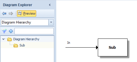
1. Connect a connector into the diagram element:
2. Go down to the child diagram.
3. Right-click the diagram area and select Set Diagram Properties...
4. Switch to the Interface Mapping tab:
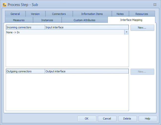
5. If there are no interface elements on the diagram, click New... to create a new input interface. Then, when you have an input interface element on the diagram, select the input interface for the connector from the Input interface drop-down menu:
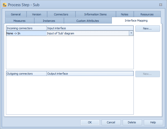
6. Click OK. You now have the incoming connector mapped to the input interface and the incoming flow is hidden from the diagram.
How to Map Connectors to Interfaces on the Interface Mapping Tab - The Shortcut
1. Connect a connector into the diagram element while holding the Ctrl key down:
2. This will open the Interface Mapping tab of the diagram element straight away:
3. If there are no interface elements on the diagram, click New... to create a new input interface. Then, when you have an input interface element on the diagram, select the input interface for the connector from the Input interface drop-down menu:
4. Click OK. You now have the incoming connector mapped to the input interface and the incoming flow is hidden from the diagram.