|
|

Diagram View Settings Properties Dialog |

|

|

|
||
Diagram View Settings Properties Dialog |
|
|
|

|
|
|
Diagram View Settings Properties Dialog |
|
|
|
||
Diagram View Settings Properties Dialog |
|
|
|
|
|
|
||
In the Diagram View Settings Properties dialog you can configure new or existing view settings. This dialog is accessible from the Custom Views dialog. In case the Diagram View is open, the dialog can be opened also by right-clicking an empty area on the diagram and selecting the "View Settings" menu item from the pop-menu or by clicking the View Settings button on the View tab of the ribbon.
General
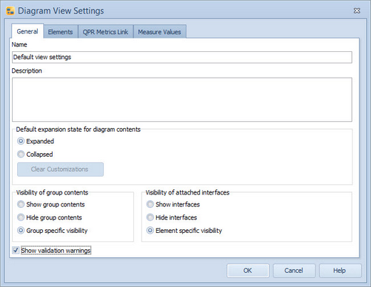
In the General tab you can define general properties for selected view settings. The properties you can define are Name, Description and the default expansion state for contents of expanded child diagrams.
The options for the default expansion state for child diagrams contents is either "Expanded" or "Collapsed". If you select the “Expanded” option, all expanded child diagrams are shown in expanded state. You can still collapse individual child diagrams on the diagram, overriding this setting. Selecting the same view setting again will reset the child diagrams to the expanded state.
You can save the change you have made to the default expansion state by selecting the "Save State to View Settings" option from the pop-up menu in the diagram. If you want to clear this setting, select the Clear Customizations button in the Diagram View Settings Properties dialog. This button has an effect only on the default expansion state for child diagram contents, not to any other changes you may have made to view settings.
The Visibility of group contents options are used to control how the contents of Group Elements are shown in the view, the "Show group contents" option will make all groups show their contents regardless of the individual group setting, the "Hide group contents" option will make all groups hide their contents regardless of the individual group setting, and the "Group specific visibility" will let the individual group setting define whether the contents are shown or not.
The Visibility of attached interfaces options are used to control how interface elements attached to other elements are shown in the view. The "Show interfaces" option will make all elements show their attached interface elements regardless of the individual element setting, the "Hide interfaces" option will make all elements hide their their attached interface elements regardless of the individual element setting, and the "Element specific visibility" will let the individual element setting define whether the attached interface elements are shown or not.
To enable the validation warnings, select the Show validation warnings check box. For more information about validation warnings, see the Modeling Options Dialog.
 +
+
Elements
In the Elements tab you can define the types of elements that are visible on the diagram when the selected view settings are active. In addition, you can define which fields within those element symbols are visible as well as limit the visibility of connectors based on their transfer types.
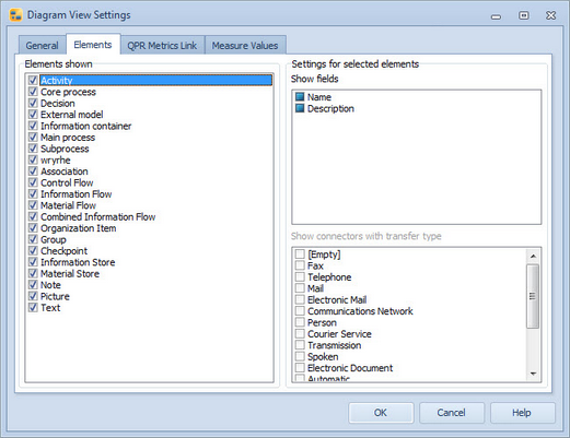
To define the elements that are shown in the view settings, use the check boxes next to the element type names in the "Element shown" section. Fields available for element type(s) (you can use Ctrl and Shift keys to select multiple types) selected in the "Elements shown" section are listed in the "Show fields" section, and there you can use the check boxes next to the field names to define the visibility of the fields. A checked box means that the field is shown for all selected types in the current view settings (i.e. the currently highlighted element types, not those that are checked) while a cleared box means that the field is not shown. In the case the box is filled, the default settings for the element type symbol are used. The default settings can be defined in the Modeling Options dialog or the element's Graphical Properties dialog.
![]()
![]()
QPR Metrics Link
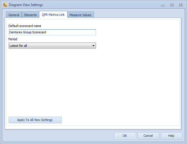
In the Metrics Link tab you can define QPR Metrics Link settings for the view. The Default scorecard name setting allows you to define a default scorecard which is used in the case of links where only measure symbol is defined. The scorecard can still be changed in QPR Portal. In addition, the Period drop-down box allows you to define the period which is used for the measure values. "Latest for all" uses the latest period for which measures have a value, and "Current" uses the current period regardless of whether it contains a value. If you want to use the settings you have defined in this dialog for all view settings, not just the current view settings, click the Apply to All View Settings button.
Measure Values
In the Measure Values tab you can define the Measure and Case for which possible measure values (these are not the same as measure values coming from QPR Metrics links) are displayed. When the measurement unit is a number value, the number of decimals can be specified using the scrolling arrows next to the Number format field.
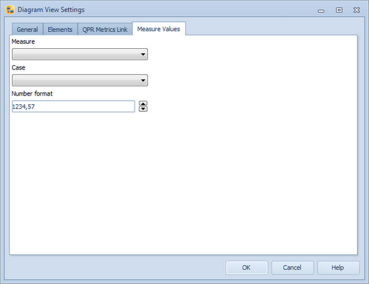
Diagram Layout Settings on the View Tab of the Ribbon
When the Diagram View is active, additional diagram view properties are available in the Diagram group on the View tab of the ribbon:
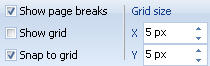
Page breaks are visible on all open diagrams if the Show page breaks checkbox is selected. The grid can be viewed on all open diagrams by selecting the Show grid checkbox. To have elements tied on the grid points, select the Snap to grid checkbox. The default grid size in the diagram is 10 by 10. To define a different grid size for all open diagrams, modify the X and Y values of the "Grid size".