|
|

Connector Type Dialog |

|

|

|
||
Connector Type Dialog |
|
|
|

|
|
|
Connector Type Dialog |
|
|
|
||
Connector Type Dialog |
|
|
|
|
|
|
||
The Connector Type dialog is used to create new flow and connector types and modify their properties. The Connector Type dialog can be opened from the Modeling Options dialog.
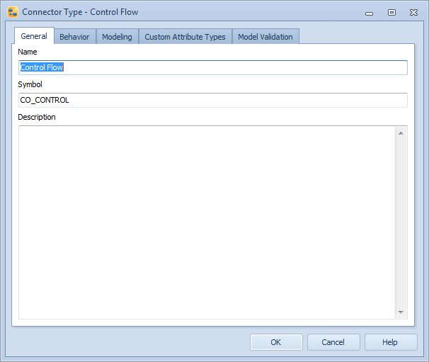
Connector Type dialog
General
A connector type can be assigned a name, a symbol and a description.
The symbol is a unique identifier for the connector type. When a new connector type is created, QPR Modeling Client will assign it a unique symbol by getting the model object id and adding "MO" to its beginning. It is also possible to edit the symbol for the connector type. Allowed characters are alphanumeric characters in upper case and lower case.
Behavior
The Behavior tab shows the predefined behavior options for the connector type and the custom hierarchies in the model.
You can select the desired behavior options for the connector type by clicking a checkbox next to the behavior option. If the option is grayed out and thus unavailable, you cannot currently modify its selection. This is usually due to some related option being selected or if the combination of behaviors is impossible in the current context.
The behavior options are:
•Information flow: the connectors of the type "Information flow" can carry an information item and, if they do, are assigned the name of the assigned information item. If a new connector type is created as an "Information flow", then it will be added as a stencil to the Tool Palette with ![]() as its symbol. Whereas regular connector types are depicted with
as its symbol. Whereas regular connector types are depicted with ![]() as their stencil symbol.
as their stencil symbol.
•Generic connector: the connectors of the type "Generic connector" can be drawn in the diagram between any elements except organization units, checkpoints, pictures, and text elements. In the case the "Generic connector" option is not selected, the connector can be connected to process steps, generic elements, and stores only. If the flow type is a "Generic connector", the start or end points of the connector cannot be edited in the Connector Dialog.
•Relation (single occurrence): the connector can be used to define relation type custom attributes. The relation can be either of the type single occurrence or multiple occurrences, not both. See the 'Relation' section below.
•Relation (multiple occurrences): the connector can be used to connect two elements. There is a relation between elements A and B that is defined by a relation connector of this type, and an instance of A exists on the same diagram as an instance of B. See the 'Relation' section below.
•Draw relations automatically: when this option is set and there is a relation of type multiple occurrences, a connector will be automatically drawn between the two elements on that diagram. If there are multiple instances of related elements on the diagram, each instance will be connected to an instance of the other element. If there are multiple instances of the target element, the closest instance will be connected. If this option is turned off for a connector type when there are automatically drawn relation connectors, all connectors of the type remain drawn. To enable this setting, you also need to select the check box "Relation (multiple occurrences)". This option is not possible when "Relation (single occurrence)" has been selected.
•Hide connectors between groups and grouped elements: when this option is set, connectors of this type will not be drawn for elements that are in a group.
•Cross-model interface: the connector can be a cross-model interface.
•Instances can have different graphical properties: when this selection is enabled, changing the graphical properties of an instance does not apply the change to every instance of the element.
•Show in child diagrams: when this option is set, the connector will be shown on the sub-diagram level when it is not connected to a diagram element. This option is not possible if the check box "Relation (multiple occurrences)" has been selected.
Element hierarchies
The element hierarchies can be used, for example, to model the structure of the process. The element hierarchies are visible in sub-tabs of the Processes tab in QPR Portal. In case the model containing the custom hierarchy is a base model, the hierarchy is published if a process step that is a part of the hierarchy is published. The "Custom hierarchies" list shows all the custom hierarchies in the model. The list is used to define element hierarchy behavior for the process step type. The list contains four parts:
•Checkbox: selecting a checkbox will make the connector type a part of the hierarchy in question.
•Hierarchy: this column lists the names of the element hierarchies in the model.
•Part of branch: the drop down boxes in this column define if the connector can be a part of a single branch (i.e. the connector can have only one parent element) or multiple branches (i.e. the connector can have multiple parent elements).
•Node type: defining the node type as a "leaf node" prevents the connectors of this type from having child elements, whereas defining the node type as "any node" allows the connectors of this type to have child elements.
Relation
The Relation tab contains trees that show all the element types in the model. Relation type custom attributes of an element type are shown under the element type. Selections on the trees define whether the connector can connect to elements of that type and which relation type custom attributes can be defined with the connector. When a connector is drawn between two elements, the selected relation type custom attributes in the elements are automatically defined for both elements.
Note: If a relation defined for the element type is of cardinality 1 and already has a value, the connector can't be connected. In addition, if a relation has been drawn between two elements, it is not possible to draw a second relation of the same type between the two elements.
Relations can now be defined to be of either single occurrence or multiple occurrences type. In the case of multiple occurrences, you can draw the connector explicitly between the elements to set the relation between the elements. Both of these types cannot be selected at the same time, so you must choose only one. If in a previously created model only the generic "Relation" type had been selected, it now refers to the single occurrence relation type. But if "Relation" and "Draw relations automatically" had been chosen in a previously created model, they are now equal to the multiple occurrences relation type with "Draw relations automatically" option enabled.
Modeling
On the Modeling tab, you can choose to show or hide the connectors on upper diagrams by selecting de-selecting the Show connectors on parent diagrams check box. This setting defines whether connectors that go from a model element in a diagram to another model element in a different diagram are shown on the parent diagrams.
The default graphical properties of the connector type are also shown. Click the Edit... button to modify the graphical properties.
Custom Attribute Types
Custom attribute types can also be defined for the connector type. On the Custom Attribute Types page of this dialog, you can add custom attribute types by clicking the "Add" button and remove custom attribute types with the "Remove" button. You can also edit the custom attribute types. To change the order of the custom attribute types, use the upward and downward arrow buttons on the right side of the dialog. You can edit the name of the custom attribute type by typing it into the Name column. The cardinality can also be changed by clicking on the cardinality value and then selecting a new value from the drop-down list (either 1 or N). If you select 1, only one value can be defined for that attribute. If you select N, several values can be defined.
If the Metamodeling Browsing feature has been enabled by your license, the number of elements (of this particular type) having values for the attribute type is shown in its own column. You can view more detailed usage information by clicking the Information... button.
![]()
![]()
Model Validation
On the Model Validation tab, you can define validation rules to help you with model consistency and following a modeling notation. When the check box is filled, the validation definition set in Modeling Options Dialog are used. When the check box is checked, the validation definition on the current element type dialog is used. See the Modeling Options Dialog topic for details.