|
|

Process Step Type Dialog |

|

|

|
||
Process Step Type Dialog |
|
|
|

|
|
|
Process Step Type Dialog |
|
|
|
||
Process Step Type Dialog |
|
|
|
|
|
|
||
The Process Step Type dialog is used to view and modify the process step type properties.
![]()
![]() In the case multilingual modeling has been enabled, click the
In the case multilingual modeling has been enabled, click the ![]() button to open the Translation dialog for adding translations for different languages. You can translate items which are inputted into the model, i.e. items such as element names, flow names, resource names, etc. The
button to open the Translation dialog for adding translations for different languages. You can translate items which are inputted into the model, i.e. items such as element names, flow names, resource names, etc. The ![]() button opens the translation dialog with the translatable strings of the current tab included. Note that the fields display the values of the currently selected modeling language, i.e. in the case translation has not been provided for the active modeling language, the fields are empty.
button opens the translation dialog with the translatable strings of the current tab included. Note that the fields display the values of the currently selected modeling language, i.e. in the case translation has not been provided for the active modeling language, the fields are empty.
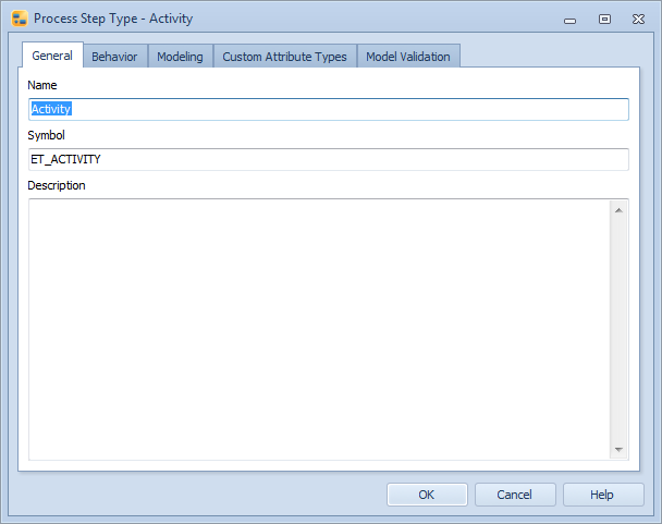
Process Step Type dialog, General tab
General
A process step type can be assigned a name, a unique symbol, a type and a description.
The symbol is a unique identifier for the process step type. When a new process step type is created, QPR Modeling Client will assign it a unique symbol by getting the model object id and adding "MO" to its beginning. It is also possible to edit the symbol for the process step type. Allowed characters are alphanumeric characters in upper case and lower case.
Behavior
The Behavior tab shows the predefined behavior options for the process step type and the custom hierarchies in the model.
You can select the desired behavior options for the process step type by clicking a checkbox next to the behavior option. If the option is grayed out and thus unavailable, you cannot currently modify its selection. This is usually due to some related option being selected or if the combination of behaviors is impossible in the current context.
The behavior options are:
•Information container: When an element with the "Information container" behavior is created, an information item is requested to be attached as well, and the initial name of the element is the name of the primary information item attached to the information container. In addition, information containers have the special characteristic of appearing in the Navigator and element selection views with a specific icon, ![]() , and they are not visible in the Report view.
, and they are not visible in the Report view.
•External model: the element can be linked to external models.
•Diagram: allow the step to be modeled in more detail on a lower level.
•Hide from diagram hierarchy: if you do not want diagrams to be visible in the diagram hierarchy view, select this setting. By default, diagrams are visible in the diagram hierarchy view.
•Show pick list when creating elements: when this selection is enabled, creating instances of process steps of this type can be done by selecting the name of an existing process step from the drop-down menu displayed on a newly created process step.
•Instances can have different graphical properties: when this selection is enabled, changing the graphical properties of an instance does not apply the change to every instance of the element.
•Allow attached elements: you can attach any element to the boundary of the element in the diagram so that they together form a group. (See the attached elements section for more information.) You also need to select this option if you want to define interface relations for the process step type.
•Allow attaching to elements: the element can be attached to any element so that they together form a group. (See the attached elements section for more information.)
•Group element: a process step of this type can be a Group Element.
•Synchronize group instances: when this option is selected, instances of Group Element of this type are synchronized.
•Can belong to a group: a process step of this type can be added to a group.
•Cross-model interface: you can define the process step of this type to be a cross-model interface.
•Allow attached interfaces: when this option is selected, interface relations can be defined for the custom element of this type by attaching interface elements to it. To enable this, you also need to select the check box "Allow attached elements".
•Allow connector mapping: when this option is selected, incoming connectors can be mapped to input and output interfaces on the diagram. To enable this, you also need to select the check box "Diagram".
•Input interface: you can define the process step type to be an input interface. To enable this, you also need to select the checkboxes "Allow attaching to elements" and "Allow multiple instances".
•Output interface: you can define the process step type to be an output interface. To enable this, you also need to select the checkboxes "Allow attaching to elements" and "Allow multiple instances".
Element hierarchies
The element hierarchies can be used, for example, to model the structure of the process. The element hierarchies are visible in sub-tabs of the Processes tab in QPR Portal. In case the model containing the custom hierarchy is a base model, the hierarchy is published if a process step that is a part of the hierarchy is published. The "Custom hierarchies" list shows all the custom hierarchies in the model. The list is used to define element hierarchy behavior for the process step type. The list contains four parts:
•Checkbox: selecting a checkbox will make the process step type a part of the hierarchy in question.
•Hierarchy: this column lists the names of the element hierarchies in the model.
•Part of branch: the drop down boxes in this column define if the process step can be a part of a single branch (i.e. the process step can have only one parent element) or multiple branches (i.e. the process step can have multiple parent elements).
•Node type: defining the node type as a "leaf node" prevents the process steps of this type from having child elements, whereas defining the node type as "any node" allows the process steps of this type to have child elements.
To create a new element hierarchy, click the New button. To view and modify the properties of an existing hierarchy, click the View button. Click Delete to delete the selected hierarchy.
Group Relations
The Group Relations tab is visible when the "Group element" behavior option is enabled. The Group Relations tab is used to select which relation type custom attributes are set in the Group Element when an element is added to the group.
Interface Relations
The Interface Relations tab is visible when both "Allow attached elements" and "Allow attached interfaces" options are enabled. The Interface Relations tab is used to select input interface relations and output interface relations of the process step type shown with all relation type custom attributes that the type has.
You cannot select the same relation for both input and output relation. Interface relations are validated when the model is opened as it is possible to create conflicting options when it has been edited by two users (for example, one user removes attribute type and another user selects it as an interface relation). If the same relation has been selected for input and output relation, the output selection is cleared after model opening. If you remove a custom attribute from the model or from the type, it is also removed from these relation lists.
If you have defined interface relations for the process step type, you cannot set input or output interface behavior for that process step type.
Modeling
The selections on the Modeling tab are used to define quick modeling settings:
•Default connector type: defines which connector type is used when a new element of this type is created using quick modeling.
•Horizontal offset: defines the horizontal distance of the created element from the selected element in pixels. Allowed values are 10 to 1000. If the grid is enabled, the offset is rounded up to the next grid size.
•Vertical offset: defines the vertical distance of the created element from the selected element in pixels. Allowed values are 10 to 1000. If the grid is enabled, the offset is rounded up to the next grid size.
In addition, the Modeling direction of the process level can be set (supported only for subprocess elements and elements that have the Hierarchy Modeling Behavior option enabled).
![]()
![]() The Default type group can also be selected if the process step is a subprocess element or if the Hierarchy Modeling Behavior option is enabled. Type groups are available with a separate license.
The Default type group can also be selected if the process step is a subprocess element or if the Hierarchy Modeling Behavior option is enabled. Type groups are available with a separate license.
The default graphical properties of the element type are also shown. Click the Edit... button to modify the graphical properties.
Custom Attribute Types
Custom attribute types can also be defined for the process step type. On the Custom Attribute Types page of this dialog, you can add custom attribute types by clicking the Add... button and remove custom attribute types with the Remove button. You can also edit the custom attribute types. To change the order of the custom attribute types, use the upward and downward arrow buttons on the right side of the dialog. You can edit the name of the custom attribute type by typing it into the Name column. The cardinality can also be changed by clicking on the cardinality value and then selecting a new value from the drop-down list (either 1 or N). If you select 1, only one value can be defined for that attribute. If you select N, several values can be defined.
If the Metamodeling Browsing feature has been enabled by your license, the number of elements (of this particular type) having values for the attribute type is shown in its own column. You can view more detailed usage information by clicking the Information... button.
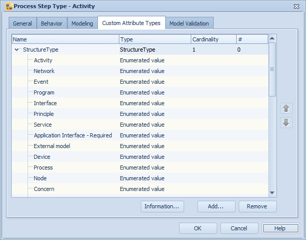
Process Step Type dialog, Custom Attribute Types tab
![]()
![]()
Model Validation
On the Model Validation tab, you can define validation rules to help you with model consistency and following a modeling notation. When the check box is filled, the validation definition set in Modeling Options Dialog are used. When the check box is checked, the validation definition on the current element type dialog is used. See the Modeling Options Dialog topic for details.